Weather

Temperature
Mont Blanc Tunnel traffic


Weather
Temperature
Mont Blanc Tunnel traffic
A comprehensive safety system
Prevention, surveillance and detection, intervention: the principles of safety
With a length of 11.6km, the Mont Blanc Tunnel is constructed from one tube through which the traffic flows in both directions. A link between France and Italy, its crossing needs a dozen minutes.
- Date open to traffic: 19th July 1965
- Length: 11,611 km
- Width at base: 8,6 m
- Width at road level: 7 m
- Number of safety shelters: 37 pressurised safety shelters all linked to a rescue gallery
- Altitude of the entry aprons: 1.274 m (France) and 1,381 m (Italy)
- Maximum altitude:: 1.395,5 m (in the middle of the tunnel)
- Thickness of the vertical rock: more than 2 km over more than half the length
- Crossing time: 12 minutes at 60 km per hour

- 50 kph MIN speed
- 70 kph MAX speed
- 150 m inter-distance
- 20 FM radio frequencies
- 2 regulation and control areas for heavy vehicles (buses and lorries)
- at Passy-Le Fayet (France), 22 km from the tunnel
- at Aosta (Italy), 44 km from the tunnel
- 2 thermo graphic gates to check any overheating of engine parts of lorries and buses
- 1 speed measurement and sanctioning system: the portion of tunnel on French territory is controlled by 6 instant speed detection radars (6 in each direction of traffic); the portion of tunnel on Italian territory is controlled by an average speed detection system installed on both directions of traffic
- 4,640 lights placed every 5m
- 2 10MW electricity lines assuring permanent supply to the entire site
- 20 Variable message boards on the ceiling
- 2 control and command posts: 1 CCP active (run by 2 operators, assuring the traffic control in the tunnel and on the aprons, who control the equipment in the tunnel) + 1 CCP traffic (run by 1 operator, who is responsible for the information and traffic conditions on the access routes)
- 35 000 data items read from different sensors, analysed by the centralised technical management
- 1 thermometric cable equipped with 3 680 sensors running the full length of the tunnel: linked to the centralised technical management, it detects the temperature in the tunnel continuously every 25 metres, through readings taken every 12 seconds
- 120 video-surveillance cameras inside the tunnel linked to a system which automatically detects incidents (this relays the irregularities detected on to the screens for the operators at the control and command post)
- 37 cameras installed in the emergency parking areas
- 1 network of sensors linked to the centralised technical management
- 20 anemometers on the ceiling to measure wind speed
- 20 opacity meters to analyse the luminosity and detect the presence of smoke
- 20 pollution sensors: CO (carbon monoxide) and NO2 (nitrogen dioxide)
- 3 intermediate intervention posts (based on the two aprons and at the centre of the tunnel), equipped by officers qualified to fight fires in confined spaces
- 4 fire-fighting intervention vehicles (Proteus)
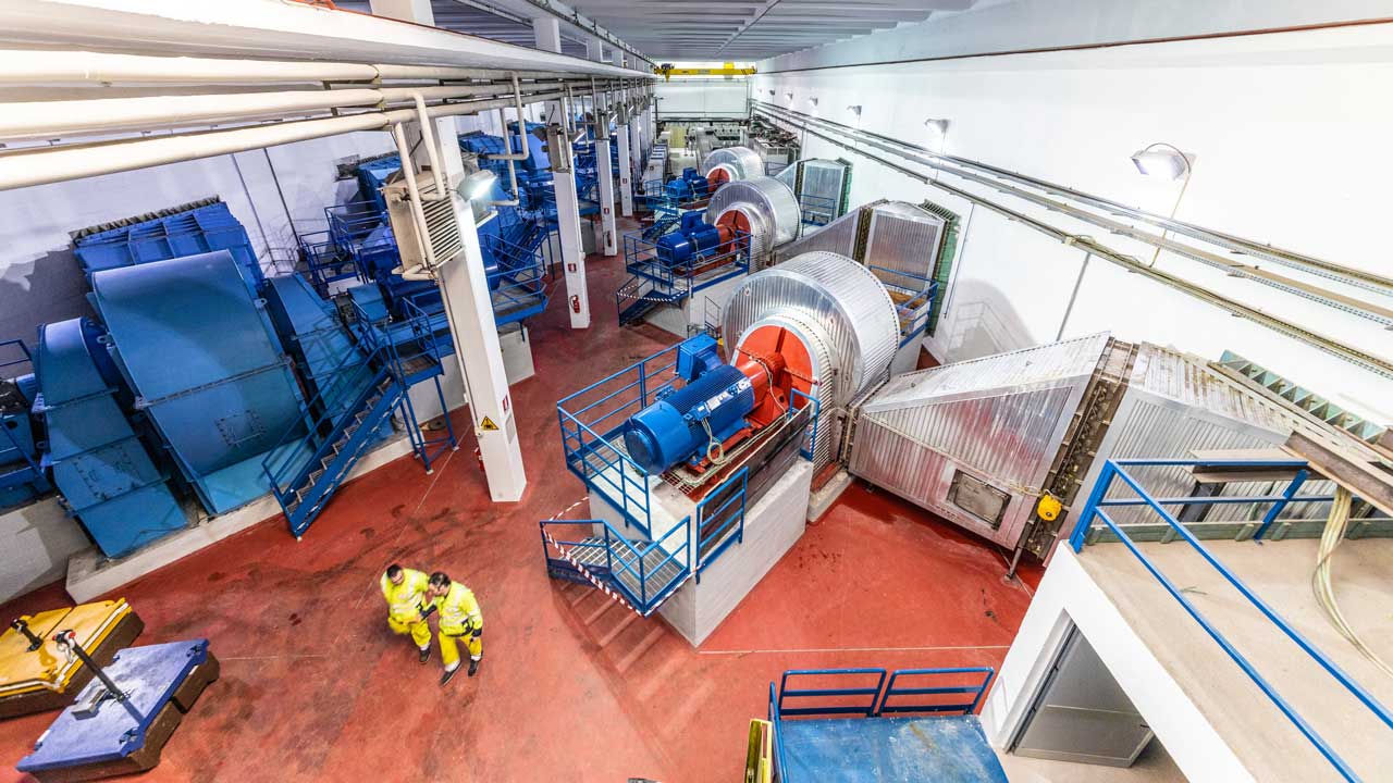
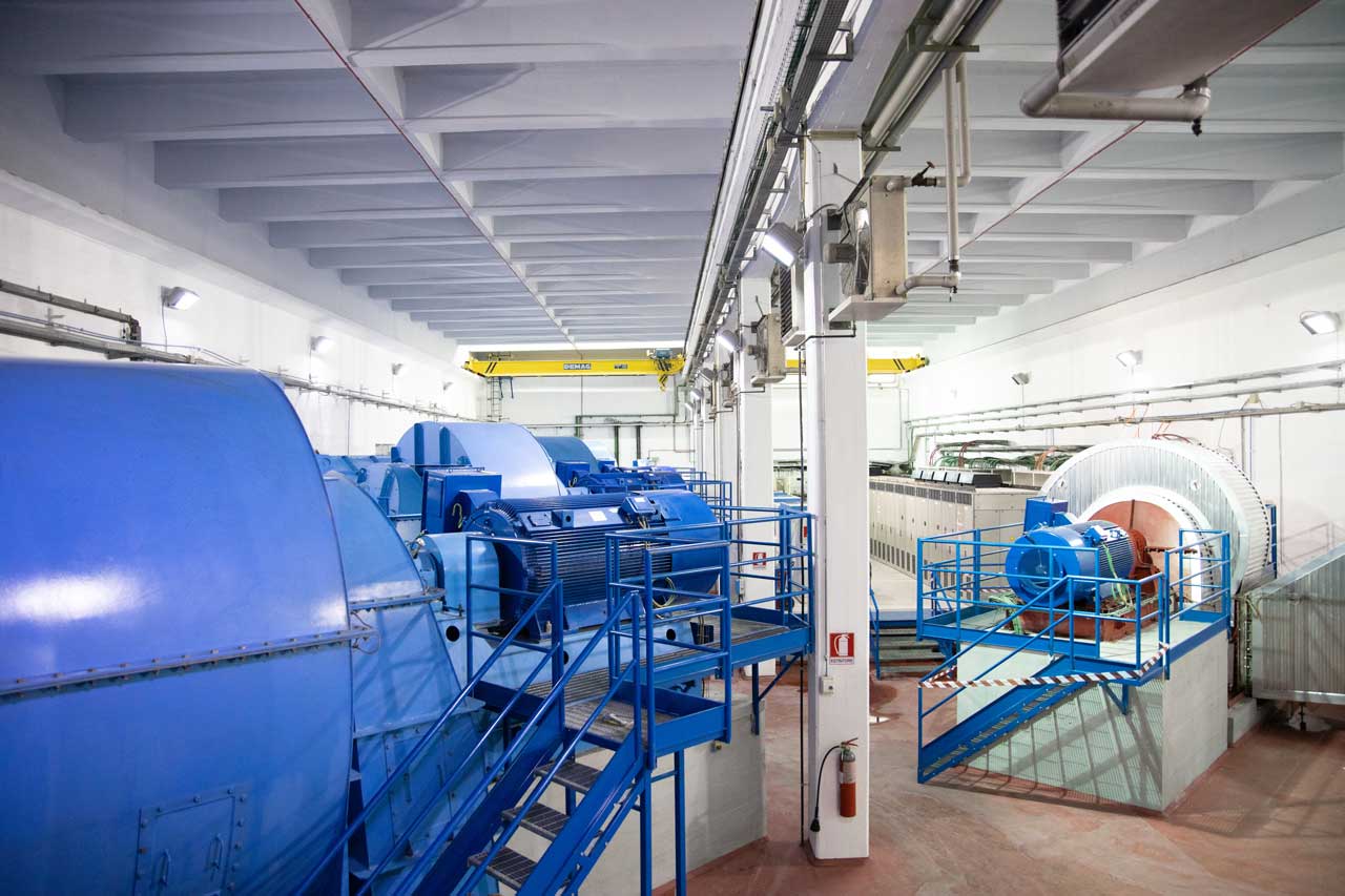
- 1 completely computer-aided ventilation system, from detection to extraction. Comprising of:
- Injection of fresh air:
- 2 power plants situated on the 2 aprons, with each 4 fresh air ventilators (+ 1 emergency back-up) with a flow varying from 25 to 82 m ³ per second
- These ventilators feed the ventilation ducts (4 on the French side and 4 on the Italian) positioned under the road each covering 1.450 m and having vents blowing air every 10m along the right-hand side Italy-France
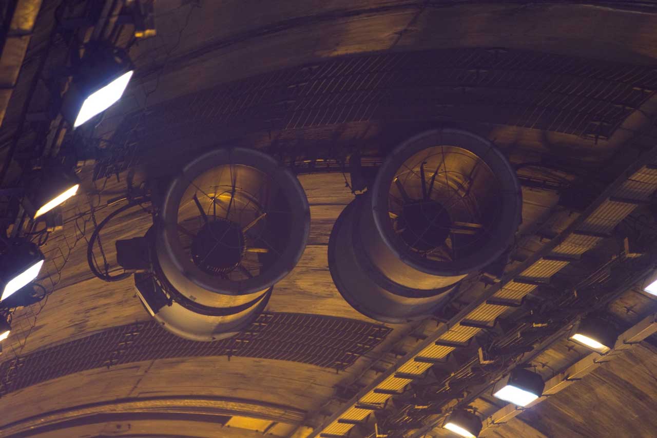
- Smoke extraction (156 m3 per second per 600m linear section):
- 1 smoke extraction duct along the full length of the tunnel
- 2 power plants situated on the two aprons, each with 2 smoke extraction ventilators (+ 1 emergency back-up)
- 4 « relay » ventilators placed inside the duct (at the level of the emergency parking areas 6, 14, 22 and 30)
- 116 smoke extraction traps with ceiling vents, every 100m, opened by remote control to raise the power of smoke extraction over each 600m section
- Management of the longitudinal air speed:
- 20 anemometers placed every 600m, which permanently measure the longitudinal air speed in the tunnel
- 76 ceiling fitted booster fans, operational in one direction at a time, manage the longitudinal air speed, managed by the centralised technical management
- 1 device for stopping traffic flow, comprising of:
- 2 entrance barriers
- 40 half barriers (one every 600m), (associated with a variable message board)
- 120 traffic lights
- 20 double faced, ceiling mounted, variable message boards (one every 600 m)
- 20 FM radio frequencies broadcast within the tunnel
- 116 SOS booths indicated by lit panels, placed every 100m and equipped with 2 fire extinguishers and one emergency telephone for alerting the control and command post
- 37 safe shelters, one every 300m, each having a surface area of around 40 m². The safe shelters are hermetically insulated and guarantee customer safety before evacuation. The interiors are supplied with pressurised fresh air and are isolated from the Tunnel by two fire doors and a filter zone that prevents smoke from penetrating; safe shelters are linked to an evacuation route; they are equipped with a stock of fresh water, as well as a video-phone allowing tunnel users to be in direct contact with the control and command post
- 1 evacuation route: The fresh air channels run the entire length of the Tunnel. They are connected to the safe shelters and enable rescue teams to reach people and lead them either to the first safe location a long way from the site of the accident, or to one of the two aprons.. Bi-direction electric vehicles can travel along these channels and are able to carry one stretcher or seat more than one person.
- 36 emergency parking areas, one every 600m per direction
- 1 water supply system, comprising of:
- 1 pressurised water pipe running the length of the tunnel
- 79 fire-fighters’ booths every 150m on the right hand-side France -Italy
- 37 supplementary booths in the safe shelter lobbies
- 4 water reservoirs of 120 m3: 1 at each of the 2 aprons and 4 in the tunnel at garages 15 and 29
Prevention by adopting minimum operating conditions (MOC)
For example, the partial or total unavailability of more than 7 pairs (out of 38 pairs) of ceiling extraction vents – used in the presence of smoke to hinder air currents along the length of the Tunnel and thereby prevent the smoke from spreading – means that MOC 307 has been exceeded and, consequently, immediate road closure is put into effect as a precautionary measure; if the number of pairs is 7 or less, normal Tunnel operation can be continued only on condition that the malfunction is repaired within a week; if the repair takes more than 7 days, it is up to the management committee to decide whether or not to adopt compensatory operational measures.
Another example concerns the difference in pressure between the two entrances to the Tunnel: when it exceeds 750 Pascal for more than 30 minutes, the road is closed to heavy vehicles as a precautionary measure aimed at reducing traffic.
The MOC are systematically monitored in order to analyse and, as a consequence, carry out ordinary system maintenance in advance.